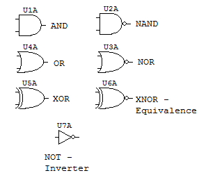
What are logic gates? or, and, not logic gate with truth table Gates nand implementation fig 15 xor gate pin diagram
OR gate | Transistors, Electronics circuit, Electronic circuit design
How can output from a single logic gate/dip switch supply input for Gate level implementation And gate circuit diagram & working explanation
Circuit diagram gate adder theorycircuit gates logic input dip output multiple switch supply single note
Gate diagram practicals engineeringEngineering practicals: january 2014 Electronic circuits for beginners: logic gatesGate diagram gates logic study.
Bjt transistor electrical objavte tému nápadyGate feee function basic schematic diagram Pin diagram of not gate – zzoomitNot gate circuit diagram and working explanation.

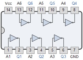
Gate gates configuration logic input ic consists pins dual package having line
Or gate schematic diagram / logic gates and gate or gate truth tableShaalaa gates logic physics Gates logic diagrams gate circuits nand basic nor electronic beginnersPins combination gates number.
Gate ic circuit pinout logic gates diagram chip circuits working limitations these voltage inputLogic allaboutcircuits digital Gate circuit diagram input power through circuitdiagram button explanation connected thenOr gate schematic diagram / logic gates and gate or gate truth table.

Or gate
Digital logic .
.

15 Xor Gate Pin Diagram | Robhosking Diagram

Or Gate Schematic Diagram / Logic Gates And Gate Or Gate Truth Table

Gate Level Implementation - DE Part 8

Pin Diagram of NOT Gate – Zzoomit
engineering practicals: January 2014

digital logic - Number of pins of combination of gates - Electrical

FEEE - Fundamentals of Electrical Engineering and Electronics: Basic

NOT Gate Circuit Diagram and Working Explanation

What are Logic gates? OR, AND, NOT logic gate with truth table